
Calculation of required airflow for the working face
The precise required airflow for the working face needs to be decided in accordance with the related provisions of the Coal Mine Security Rules and the AQ1056-2008 Commonplace for Coal Mine Air flow Capability Verification. The required airflow of a completely mechanized working face is calculated individually based mostly on fuel and carbon dioxide emissions, in addition to the working-face air velocity and the variety of personnel. The utmost worth amongst these calculations is then used for air velocity verification17.When the necessities are happy, this most worth is taken because the precise required airflow for the working face.
Calculation based mostly on on-site meteorological situations
$$Q_{met} = 60 cdot v_{cf} cdot S_{eff} cdot K_{h} cdot K_{l} cdot K_{s}$$
(1)
Within the equation:
(Q_{met})— required airflow for the coal mining working face, in m3/min; (v_{cf})— air velocity on the coal mining working face. For absolutely mechanized faces, with the consumption airflow temperature beneath 20 °C, the working-face air velocity is usually taken as 1m/s.
(S_{eff})— the common efficient cross-sectional space of the coal mining working face, calculated as the common of the utmost and minimal supported efficient cross-sections multiplied by the efficient air flow peak, leading to 14.85 m2.
(K_{h})— adjustment coefficient for the mining peak of the working face. To make sure an applicable airflow velocity, it’s taken as 1.2.
(K_{l})— adjustment coefficient for the size of the working face. For a face size of 276.0 (m), it’s taken as 1.5.
(K_{s})— coefficient of efficient air flow cross-Sect. 70%.
Due to this fact, (start{aligned} Q_{{met}} & = 60 occasions v_{{cf}} occasions S_{{eff}} occasions K_{h} occasions K_{l} occasions K_{s} & = 60 occasions 1 occasions 14.85 occasions 1.2 occasions 1.5 occasions 70% & = 1122.66({textual content{m}}^{3} /{textual content{min}}) finish{aligned}).
Calculation based mostly on fuel emission charge
Within the equation:(q)—absolute fuel emission charge within the return-air move of the coal mining working face, in m3/min. Based mostly on the 2024 fuel classification evaluation report, the measured worth from adjoining and comparable working faces was taken as 0.42 m3/min;(Ok)—extra airflow coefficient accounting for uneven fuel emission within the coal mining working face. Throughout regular manufacturing, it’s decided by constantly observing the each day most absolute fuel emission and the month-to-month common each day absolute fuel emission over one month; the ratio ranges from 1.5 to 2; 100—conversion coefficient to make sure that the fuel focus within the return-air move of the working face doesn’t exceed 1%. The fuel focus within the return-air move didn’t exceed 1%, so the coefficient is taken as 100. Due to this fact: (Q_{met} ge 100q_{1} K_{1} ge 100 occasions 0.42 occasions 1.5 ge 63.0;{textual content{m}}^{3} /{textual content{min}}).
Calculation based mostly on carbon dioxide emission charge, with the formulation as follows
$$Q_{met} ge 67K_{2} q_{2}$$
(3)
Within the equation:
(q_{2})— the common absolute CO2 emission charge within the return-air move of the absolutely mechanized coal mining face. In response to the 2024 fuel classification evaluation report, the common absolute CO₂ emission charge measured within the consumption and return-air roadways of adjoining and comparable working faces is 3.22 ({textual content{m}}^{3} /{textual content{min}});
(K_{2})— reserve airflow coefficient accounting for the uneven CO₂ emission on the absolutely mechanized mining face. Throughout regular manufacturing, it’s decided by constantly monitoring for one month and calculating the ratio of the each day most absolute CO₂ emission to the month-to-month common each day absolute CO₂ emission. This ratio sometimes ranges from 1.5 to 2;
67— conversion coefficient guaranteeing that the CO₂ focus within the return-air move of the absolutely mechanized working face doesn’t exceed 1.5%;
$$Q_{met} ge 67K_{2} q_{2} ge 67 occasions 1.5 occasions 3.22 ge 323.6{textual content{m}}^{3} /{textual content{min}}$$
Verification based mostly on the variety of personnel
$$Q_{met} ge 4{textual content{N}};{textual content{m}}^{3} /{textual content{min}}$$
Within the equation: N—the variety of personnel working concurrently on the absolutely mechanized mining face, 30 individuals;4—the required airflow per individual, 4 ({textual content{m}}^{3} /{textual content{min}}). Due to this fact:
(Q_{met} ge 4N = 120;{textual content{m}}^{3} /{textual content{min}}).
In response to the above outcomes, the utmost required airflow,(Q_{met} = 1122.66;{textual content{m}}^{3} /{textual content{min}}), is adopted because the design airflow of the working face.
Verification of the required airflow
Verification of the minimal airflow
$$Q_{met} ge 60 occasions 0.25S_{cb}$$
(4)
$$S_{cb} = I_{cb} occasions h_{cf} occasions 70% ;{textual content{m}}^{2} ;Q_{met} ge 60 occasions 0.25 occasions 5.27 occasions 3.05 occasions 0.7 = 168.8;{textual content{m}}^{3} /{textual content{min}}$$
Verification of the utmost airflow
$$Q_{met} le 60 occasions 4.0S_{cs}$$
(5)
$$S_{cs} = I_{cs} occasions h_{cf} occasions 70% ;;{textual content{m}}^{2} Q_{met} le 60 occasions 4.0 occasions 4.47 occasions 3.05 occasions 0.7 , le 2290.4;;{textual content{m}}^{3} /min$$
That’s,(168.8;{textual content{m}}^{3} /{textual content{min}}; le Q_{met} le 2290.4;{textual content{m}}^{3} /{textual content{min}}), and the verification based mostly on airflow velocity meets the required requirements.
Based mostly on the calculated values, the utmost required airflow, (Q_{met} = 1122.66;({textual content{m}}^{3} /{textual content{min}})), is provisionally adopted because the verification airflow for the working face.
From the airflow verification outcomes, the obtained airflow and air velocity meet the necessities of the Coal Mine Security Rules. Throughout regular manufacturing, the utmost worth is taken because the precise required airflow for the 45,207 absolutely mechanized working face.
That’s, throughout regular manufacturing: (sum Q_{met} = Q_{{met{ 45207}}} ge 1122.66;{textual content{m}}^{3} /{textual content{min}}).
Equal-pressure structure scheme and fan choice
Collection of equal-pressure air flow route
Auxiliary stage adit → 5–2 auxiliary haulage roadway → 4-Panel Space Centralized Auxiliary Haulage Roadway → 45,208 Measure Roadway → 45,208 Auxiliary Return Withdrawal Passage → 45,208 Most important Return Withdrawal Passage → 45,208 Return Circulate → Connecting Roadway of Incline → 45,207 Haulage Incline → 45,207 Absolutely Mechanized Working Face → 45,207 Return Circulate → 45,207 Return Air Bypass → 4-Panel Space Centralized Return-Air Roadway → 4-Panel Space Most important Return → Daluomeng Return-Air Inclined Shaft → Floor.
Airflow calculation for the clever equal-pressure monitoring and dynamic regulation system
Contemplating the air leakage from the 45,208 return-air incline air doorways and the 45,207 transport incline cross-belt air doorways, the leakage from the 45,207 return-air incline air doorways on the return-air facet of the clever equal-pressure monitoring and dynamic regulation system could be uncared for. Due to this fact, the airflow of the equal-pressure fan is:
$$start{array}{*{20}l} start{aligned} Q_{{fan}} & = Q_{{met}} + Q_{{{textual content{45208 return move air doorways}}}} + Q_{{45207haulageinclineairdoors}} & = 1122.66{textual content{ m}}^{3} /{textual content{min}} + 200{textual content{ m}}^{3} /{textual content{min}} + 400{textual content{ m}}^{3} /{textual content{min}} & = 1722.66{textual content{ m}}^{3} /{textual content{min}} finish{aligned} hfill finish{array}$$
Calculation of equal-pressure air flow resistance
Mine air flow resistance refers back to the numerous resistances encountered by airflow throughout its motion inside mine roadways. It primarily contains frictional resistance alongside the roadway partitions, native resistance at roadway bends, and extra resistance attributable to obstacles reminiscent of gear and ore piles throughout the roadway18. As one of many core indicators for evaluating the operational state of a mine air flow system, the magnitude of air flow resistance is influenced by a number of elements. These embrace wall roughness, roadway geometry, bends and department constructions, obstacles reminiscent of gear and ore piles, in addition to airflow velocity and course. These elements are interrelated and act synergistically, collectively figuring out the precise air flow resistance throughout the roadway.
Within the context of equal-pressure air flow on the working face, the strain that the fan should overcome for regulation basically constitutes the core part of the air flow resistance on this state of affairs. It’s primarily composed of two components:
The primary is the along-route resistance, which, in step with the core varieties of air flow resistance, particularly contains the frictional resistance of the working-face roadways and the resistance of leakage pathways within the goaf pushed by static strain.
The second is the native extra resistance impact, particularly represented by the 350 Pa strain generated by the 45,207 return-air incline air doorways.
Frictional (or longitudinal) resistance:
The calculation of along-route resistance relies on the frictional resistance formulation supplied within the Mining Engineering Design Guide, as proven in Eq. (6).
$$h = frac{{alpha LPQ^{2} }}{{S^{3} }} = R occasions Q^{2}$$
(6)
the place: (h)—frictional resistance, (Pa);
(alpha)— frictional resistance coefficient,({textual content{N}}cdot{textual content{S}}^{2} /{textual content{m}});
(L)— roadway size,({textual content{m}});
(P)— perimeter of the roadway’s clear cross-section,(m);
(Q)— airflow by way of the roadway,({textual content{m}}^{{3}} {textual content{/s}});
(S)— clear cross-sectional space of the roadway, m2;
(R)— frictional resistance issue of the roadway, N S2/m8.
Based mostly on the beforehand decided air flow resistance outcomes, the frictional resistance coefficient ((alpha)) of the roadways was calculated. The segmented calculations of the frictional resistance for the working-face roadways are as follows.
Calculation of Alongside-Route Frictional Resistance for the 45,207 Absolutely Mechanized Working Face Air flow System.
The calculated along-route resistance of the working-face roadways is (h_{45207face} = 91.871;{textual content{Pa}}).
Calculation of Equal Resistance for Leakage Pathways within the Goaf.
Based mostly on the static strain restoration technique from hydraulic calculations of fluid distribution networks, in branched airways, the Bernoulli equation is utilized as follows:
(P_{j1} + P_{d1} = P_{j2} + P_{d2} + Delta P),The place:
(P_{j})— static strain,({textual content{Pa}});
(P_{d})— dynamic strain,({textual content{Pa}});
(Delta P)— resistance of the principle airway,({textual content{Pa}}),(Delta P_{j} = P_{j2} – P_{j1} = (P_{d1} – P_{d2} ) – Delta P);
(Delta P_{j})— recovered static strain, ({textual content{Pa}}).
When (Delta P_{j}) < 0, the strain loss within the branched airway part should be overcome by the fan. The resistance of the leakage pathways within the goaf pushed by static strain could be thought of equal to the resistance from the auxiliary stage adit to the 45,207 working face. The calculated outcomes are as follows.
$$h_{goaf , leakage} = 992.09;{textual content{Pa}}$$
Calculation of Resistance for the Equal-Strain Air flow System of the Absolutely Mechanized Working Face:
$$h_{f} = h_{45207face} + h_{goaf , leakage} = 91.871 + 992.09 = 1083.961;{textual content{Pa}}$$
Whole Resistance of Native Air flow Followers.
The resistance of the native air flow fan is the sum of the along-route resistance and the strain from the 45,207 air doorways. Due to this fact, the whole fan strain is: (1083.961 + 350 = 1433.96;{textual content{Pa}}).
Collection of fan gear
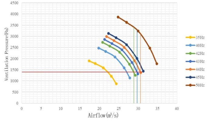
Moreover, based mostly on the beforehand measured air flow resistance, the air density on the 45,207 transport incline ((rho = 1.022;{textual content{kg}}/{textual content{m}}^{3})) was used to appropriate the fan strain underneath commonplace situations. The attribute curves of the variable-frequency fan at totally different frequencies had been plotted, as proven in Fig. 1. Two (FBD – {textual content{No}};12.52 occasions 75;{textual content{kW}}) variable-frequency equal-pressure followers had been chosen (one for operation, one as backup). The working level fan strain is 1433.9 Pa, similar to airflow charges of roughly 1740 ({textual content{m}}^{3} /{textual content{min}}) at 42 Hz, 1794 m3/min at 43 Hz, and 1848 m3/min at 44 Hz .

Working attribute curves of the FBD-№12.5 2 × 75 Kw variable-frequency equal-pressure fan.
Based mostly on the calculated airflow and fan strain, the connection amongst variable-frequency fan frequency, rotational velocity, strain, and airflow is expressed as follows:
$$frac{{Q_{1} }}{{Q_{2} }} = frac{{n_{1} }}{{n_{2} }} = frac{{f_{1} }}{{f_{2} }} cdot frac{{H_{1} }}{{H_{2} }} = left( {frac{{n_{1} }}{{n_{2} }}} proper)^{2} = left( {frac{{f_{1} }}{{f_{2} }}} proper)^{2}$$
(7)
(f)— fan frequency, ({textual content{Hz}});
(n)— fan rotational velocity, (r/{textual content{min}});
(H)— fan strain, ({textual content{ Pa}});
(Q)— fan airflow, m3/s.
The variation of native fan strain attributable to adjustments in frequency could be estimated utilizing Eq. (7). At an working level of 42 ({textual content{Hz}}), the fan strain is 1433.9 ({textual content{Pa}}). Utilizing Eq. (7), the fan strain at 43 ({textual content{Hz}}) could be estimated as (frac{{H_{1} }}{{left( {frac{{f_{1} }}{{f_{2} }}} proper)^{2} }} = frac{1433.9}{{left( {frac{42}{{43}}} proper)^{2} }} = 1502.95;{textual content{Pa}}), indicating a rise of (100 occasions frac{(1502.95 – 1433.9)}{{1433.9}} = 4.8%). Minor adjustments in native fan strain attributable to frequency variations could be balanced by the 45,207 return-flow equal-pressure adjustment air doorways. In response to the precept of fixed fan effectivity with frequency variation, the corresponding fan effectivity stays above 80%, which meets the airflow necessities of the working face. The fan’s rated airflow is 1490–2090 m3/min, adequate to fulfill the working-face air flow demand.